
Hydraulic Breaker Bushing Wear: Inspection Guide
Inspect hydraulic breaker upper and lower bushing wear, build a traceable measurement record and order the correct model-specific parts.
All buyer guides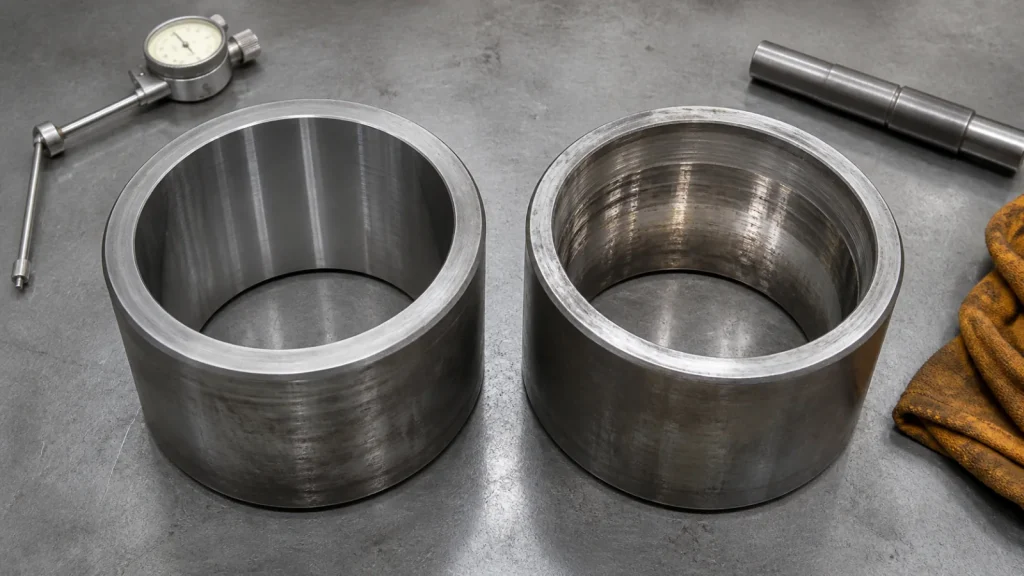
A hydraulic breaker bushing guides the working tool and helps keep it aligned with the piston and front head. Wear at this interface affects more than tool movement: it can change contact patterns, increase side loading, accelerate seal or component damage and make diagnosis harder. The correct response is not to apply one internet clearance number to every breaker, but to inspect and measure the exact model against its manual.
This guide covers the observable signs of bushing wear, the records a workshop should create, and the ordering evidence needed for upper and lower bushings. It does not provide a universal wear limit, removal method, heating temperature, press force or installation clearance.
Safety boundary: Park and isolate the carrier, support the attachment and follow the exact breaker manual before tool or retainer work. A chisel and bushing are heavy; stored pressure and pinch points remain hazards. Removal, dimensional acceptance and installation belong to trained personnel with suitable lifting and measuring equipment.
Upper and Lower Hydraulic Breaker Bushing Roles
Many breaker designs use more than one guiding element around the tool. The lower bushing supports the tool near the front opening, where abrasive material and external contamination are common. An upper bushing or inner guide supports alignment farther inside the front head. Names vary between manufacturers: “front bush,” “tool bushing,” “thrust bush,” “upper bush” and “lower bush” may not refer to identical positions.
Use the parts drawing, not terminology alone. Mark each removed bushing with its original position and orientation. The complete hydraulic breaker parts diagram helps place bushings in the overall assembly; the chisel guide separately owns tool profiles and tool selection.
- 1
Observe assembled conditionMovement, grease pattern, tool alignment and external damage
- 2
Identify every componentBreaker model/revision, tool and upper/lower bushing positions
- 3
Measure by the manualNamed locations, directions, instruments and acceptance limits
- 4
Inspect the interfacesTool, retainers, front head and contamination evidence
- 5
Order by drawingPart number, position, revision, quantity and related scope
Observable Signs That Need a Bushing Check
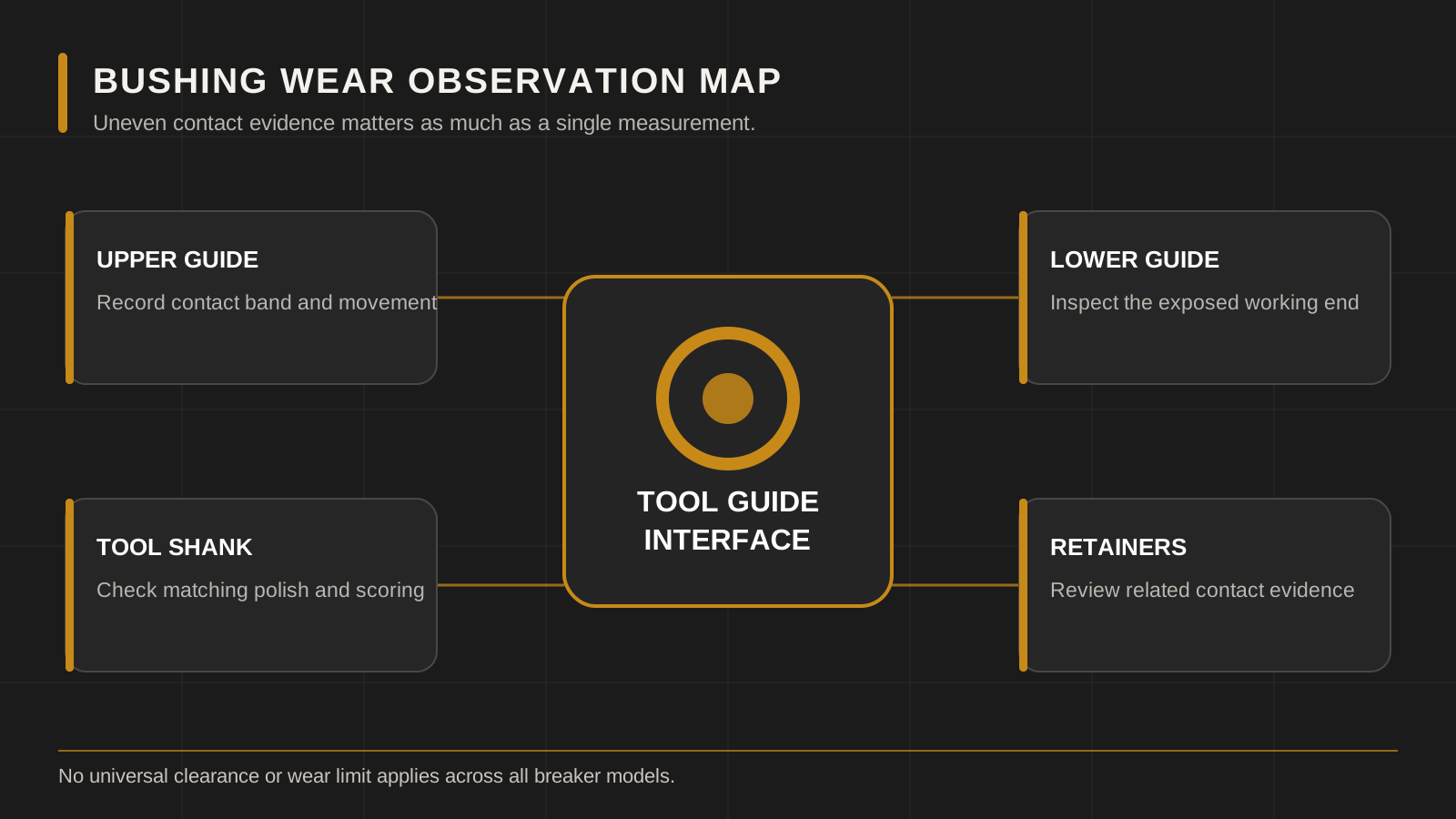
The operator can identify reasons to stop and request inspection without deciding whether a bushing has passed its wear limit. Useful observations include visibly increased side movement, uneven tool contact, abnormal metallic sound, grease escaping in a new pattern, repeated tool-retainer damage, accelerated tool shank marking or difficulty keeping the breaker aligned.
These signs are not exclusive to bushings. A wrong tool, worn tool shank, damaged retainer, loose housing, front-head damage, inadequate lubrication or poor operating angle may produce overlapping evidence. Record the entire interface before replacing one part.
Safe External Checks Before Tool Removal
- Clean the visible area safely: remove loose dirt after shutdown so cracks, grease paths and damage are visible. Do not reach into the tool opening.
- Photograph four sides: include the complete front head, tool, retainers and lower opening with a scale reference where practical.
- Record movement consistently: if the manual permits an external movement check, identify breaker position, tool position and direction. A video without setup details is not repeatable evidence.
- Inspect lubrication evidence: note dry areas, contaminated grease, abnormal escape paths and the maintenance record. Do not force grease into a damaged assembly to hide the symptom.
- Check related fasteners and housing: loose or shifted parts can imitate guide movement. Follow model-specific inspection points and torque controls.
If the tool or retainer is cracked, severely deformed or at risk of falling, remove the attachment from service and secure the area. Do not continue operating merely to create a clearer video.
How a Workshop Should Record Bushing Wear
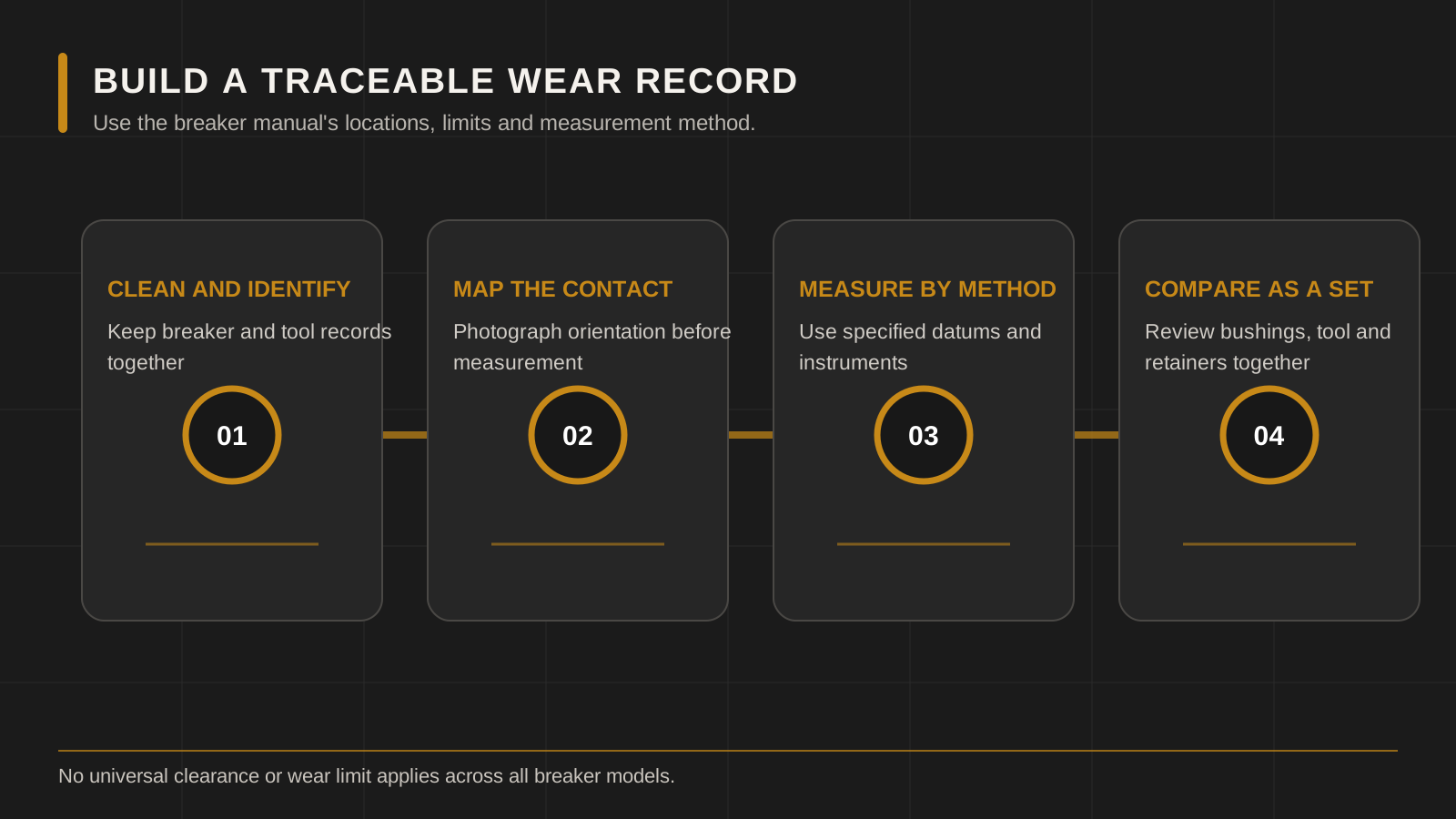
Manufacturer manuals commonly define where and how wear is checked, but the direction, reference points and limits differ. A defensible record identifies the exact manual revision and links every reading to a drawing or photograph. “Clearance 5 mm” is incomplete if it does not say which two surfaces were measured, in which direction, with the tool in which position.
| Record field | Required detail | Reason |
|---|---|---|
| Manual reference | Manufacturer, model, document/revision and inspection figure. | Prevents a limit from another breaker being reused. |
| Component position | Upper/lower or exact drawing item number and original orientation. | Names are inconsistent across designs. |
| Measurement point | Labeled location, depth and direction on a marked sketch. | Bushings can wear unevenly. |
| Instrument | Tool type, resolution and calibration status where required. | Supports repeatability and avoids ruler-based guesses. |
| Readings | Actual values, units and repeated directions; do not round to a nominal size. | Shows ovality or localized wear. |
| Mating parts | Tool-shank and front-head condition with matching photos/readings. | A new bushing cannot correct every interface fault. |
Why There Is No Universal Bushing Wear Limit
Breakers use different tool diameters, bushing lengths, guide arrangements, materials and front-head designs. Manufacturers may define acceptance as a bushing internal diameter, a tool-to-bush clearance, an external movement check or another model-specific measurement. Even within one product family, a production revision can change the relevant part number or criterion.
Use the figure and limit in the exact operator or service manual. Epiroc’s official maintenance guidance, for example, directs owners to check working-tool and wear-bushing limits for the specific attachment rather than publishing one value for every breaker. That principle is the safe boundary here: the website explains the workflow, but the approved document controls the number.
Wear Patterns and What to Investigate
Uneven wear around the bore
Uneven wear can indicate repeated side loading, poor alignment, a worn tool, debris or damage elsewhere in the guide system. Review operator technique and the full tool path; do not rotate or reinstall a part unless the manufacturer procedure expressly permits it.
Deep scoring or embedded debris
Record the direction and location before cleaning. Inspect the tool shank, lubrication condition and contamination source. Installing a new bushing without removing embedded hard debris can damage both parts.
Cracking, pieces missing or deformation
Remove the assembly from service. The workshop should inspect the front-head seat, retainers and tool for consequential damage. A replacement bushing must seat in an acceptable mating component.
Rapid repeat wear
A short repeat life is a root-cause problem. Confirm correct part identity, tool compatibility, installation record, lubrication method, working angle, carrier application and front-head condition before repeating the repair.
Bushing, Tool and Lubrication Must Be Reviewed Together
The bushing guides the tool, while grease reduces friction and helps carry contaminants away from the working interface. Too little appropriate lubrication can accelerate wear; poor cleaning and excess contaminated grease can also conceal developing damage. The hydraulic breaker grease guide explains how to build a model-specific lubrication routine without inventing one universal interval.
Inspect the tool shank at the same time. A tool that is below its approved wear criterion, bent, cracked or heavily scored can compromise a new bushing. Conversely, a worn bushing can allow abnormal tool movement. The quotation and work order should state whether the tool is accepted, replaced or pending inspection.
Information Needed to Order a Hydraulic Breaker Bushing
- Breaker brand, complete model, serial or production revision.
- Photographs of the full breaker, nameplate, front head and tool.
- Parts drawing with the upper/lower bushing item highlighted.
- Existing part number, casting/stamping marks and original position.
- Tool diameter and labeled tool-shank measurements.
- Bushing dimensions requested by the supplier, with measurement locations shown.
- Wear symptom, lubrication record and technician inspection notes.
- Required quantity, destination and any related parts to quote separately.
Do not state only “inner bush” or “front bush.” Those words may map to different positions. A marked drawing removes ambiguity before production or shipment.
When downtime matters, request separate quotation lines for the confirmed bushing, inspection-dependent companion parts and optional service consumables. This keeps the buyer from confusing a contingency item with a diagnosed replacement and makes the final shipment easy to verify against the workshop plan.
How to Review a Bushing Quotation
| Check | Good evidence | Risk signal |
|---|---|---|
| Position | Drawing item number and upper/lower location are explicit. | Quotation says only “bush” or uses an unlabeled photo. |
| Fitment | Model and serial/revision or an agreed drawing comparison controls the match. | Excavator tonnage or tool diameter is the only evidence. |
| Dimensions | Supplier drawing states the interfaces needed for confirmation. | One rounded diameter is treated as complete identity. |
| Quantity/scope | Each bushing and related part is listed separately. | Buyer assumes upper and lower pieces are a pair. |
| Commercial terms | Availability, lead time, packing, destination and terms are current and written. | A website photograph is treated as live stock proof. |
Common Bushing Service Mistakes
- Continuing to operate after abnormal tool movement becomes visible.
- Applying a wear limit copied from a different brand or tool diameter.
- Measuring only one direction and missing uneven wear.
- Replacing the guide without inspecting the tool, retainers and front-head seat.
- Mixing upper and lower positions after disassembly.
- Grinding, welding or modifying a bushing without an approved repair specification.
- Ordering by appearance instead of a drawing and breaker revision.
Copy-and-Send Bushing Request
Hydraulic breaker bushing inquiry
Breaker brand / full model / serial: ___
Tool diameter and tool part number: ___
Required position/drawing item: upper ___ / lower ___
Existing bushing marks: ___
Symptom and operating history: ___
Manual and wear-limit reference: ___
Labeled measurements attached: bushing / tool / front head
Photos attached: complete breaker / nameplate / assembled movement / removed bushing / mating parts
Quantity and destination: ___
Please confirm: fitment basis / part number / each included item / availability.
Frequently Asked Questions
How much hydraulic breaker bushing play is acceptable?
There is no safe universal value. Use the exact model manual, its stated measurement method and its wear limit.
Can I replace only the lower bushing?
That depends on the inspection and manufacturer procedure. Upper guide, tool, retainer and front-head conditions should still be checked and recorded.
Does a new bushing fix a worn chisel?
No. The tool and bushing are mating wear components. Each must meet its own model-specific acceptance criteria.
Can a bushing be matched by tool diameter?
Tool diameter is useful supporting data, but length, outside fit, shoulders, grooves, position and breaker revision can differ.
When should operation stop?
Stop when the manual’s limit is reached or when cracking, severe movement, loose/failed retention, abnormal contact or another unsafe condition is observed.
Manufacturer Reference Used for This Guide
Epiroc’s official hydraulic breaker consumables guide identifies the tool/bushing interface as a specialized wear and lubrication system. Use the exact breaker manual for measurement points and limits; the brochure is not a LICHI fitment table.
Request a Model-Matched Bushing Review
Send the marked parts drawing, breaker identity, workshop record and destination through LICHI contact. The spare-parts support page explains the full inquiry path. Final fitment, material, dimensions, service limits, availability, price, packing and lead time remain subject to written confirmation for the exact model.
Keep Comparing
Compare more breaker models and buyer guides related to this topic.


