
How to Install a Hydraulic Breaker: Acceptance Checklist
Use a documented mechanical, hydraulic and commissioning checklist to install a hydraulic breaker without guessing fitment or settings.
All buyer guides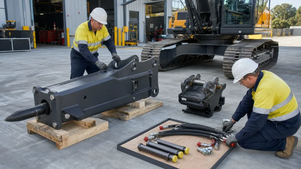
To install a hydraulic breaker safely is an acceptance process, not simply pinning an attachment to an excavator. The breaker, bracket or coupler, carrier auxiliary circuit, hoses, fittings, return path, guarding and control settings must form one documented system. A combination that physically connects can still be hydraulically or structurally unsuitable.
This guide begins after a candidate breaker/carrier combination has been selected. It explains how to install a hydraulic breaker through a pre-installation evidence pack, connection and commissioning checklist, and handover record. It does not replace the carrier, coupler and breaker manuals, and it gives no universal flow, pressure, torque, hose size or relief setting.
Safety boundary: Only competent personnel should install and commission a breaker. Isolate the carrier, secure heavy components, release hydraulic pressure by the manufacturer procedure and use rated lifting points/equipment. Never modify a bracket, coupler, hydraulic line, guard or pressure setting from an online article.
Before Installation: Confirm the Combination on Paper
Start with the exact carrier model and serial configuration, not only operating weight. Record the auxiliary hydraulic circuit, approved attachment capacity, coupler interface, line arrangement and control options. Then record the breaker model, serial/revision, operating mass in the supplied configuration, approved hydraulic requirements, bracket and hose specification.
If the combination is still being selected, use the breaker-to-excavator matching guide first. Installation should not be used to solve an unresolved capacity or hydraulic mismatch.
- 1
ApplicationCarrier capacity, breaker mass and intended material/work
- 2
Mechanical interfaceBracket/coupler, pins, locks, clearances and guarding
- 3
Hydraulic interfacePressure/return routing, flow and approved settings
- 4
Controlled testLeak, movement, control, temperature and function observations
- 5
HandoverSettings source, photos, inspection record and operator briefing
Installation Evidence Pack
Collect documents before the machine is immobilized for work. The pack should contain the carrier operator/attachment manual, breaker operator manual, coupler or bracket documentation, hydraulic-kit instructions, parts drawings and the written matching/quotation record. Confirm that document revisions match the actual serials.
| Evidence | Minimum identification | Decision supported |
|---|---|---|
| Carrier manual/data | Model, serial/configuration and auxiliary circuit details. | Capacity, control mode and approved hydraulic conditions. |
| Breaker manual/data | Full model, serial/revision and supplied configuration. | Mass, flow/pressure range, connection and inspection requirements. |
| Bracket/coupler drawing | Part/drawing revision, pin centres/diameters, widths and locking interface. | Mechanical fit, range of motion and retention. |
| Hydraulic kit drawing | Pressure/return route, hose/fitting identities and valve/filter requirements. | Correct routing, cleanliness and circuit configuration. |
| Commissioning sheet | Test method, instrument, acceptance criteria and responsible technician. | Controlled first operation and traceable handover. |
Inspect the Delivered Breaker Before Mounting
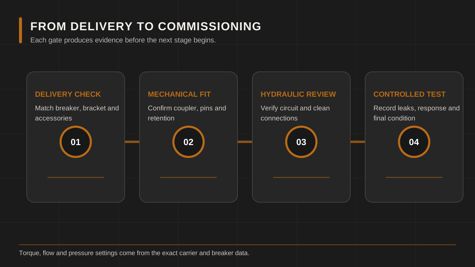
Photograph the package and breaker before removing protection. Compare the nameplate, model, body type, bracket, tool and supplied accessories with the packing list and approved order. Record transport damage, loose parts, missing protective caps or evidence that a hydraulic port was exposed.
Check the preservation and storage instructions. Do not assume a newly delivered breaker is ready for immediate operation; the manual may require lubrication, fastener inspection, gas-condition confirmation or another pre-start action. If the unit has been stored for a long period, obtain a recommissioning procedure.
Mechanical Interface Checklist
Bracket, pins or coupler
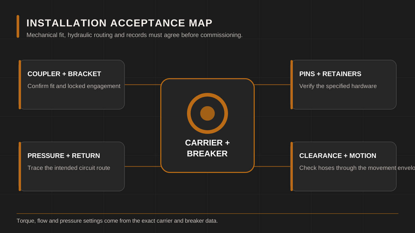
Verify the bracket drawing and part identity against the carrier interface. Inspect pin diameters, centres, boss widths, bushes, stops, locking elements and retainers using the coupler/carrier criteria. A bracket should not be forced into place, flame-cut or re-drilled on site without approved engineering documentation.
Locking confirmation
Follow the coupler manufacturer’s connection and visual/physical confirmation sequence. Record the lock indicator or retention check as required. Never rely solely on the operator hearing a click. Establish an exclusion zone before any attachment movement.
Range of motion and interference
Move through the approved range slowly, without pressurizing the breaker, to check hose paths, boom/stick interference, cab/guard clearance and transport position. Consider how hose length changes through the whole movement, not only while the attachment rests on the ground.
Mass and machine stability
Confirm the breaker’s actual operating mass, including bracket, coupler, tool and hoses, against the carrier’s attachment limits. Ground condition, reach, orientation and carrier configuration influence stability. The responsible carrier documentation controls the acceptance.
Hydraulic Connection Checklist
Keep every port and hose capped until the moment of connection. Clean tools and surrounding surfaces using the approved method, and do not push dirt inward while wiping a fitting. Identify pressure and return lines from drawings and machine markings; a hose’s physical reach does not prove its function.
- Confirm hose assembly identities, working rating, size, length, fitting type and routing against the approved kit.
- Confirm the pressure and return ports on both carrier and breaker. Tag them before connection if labels are unclear.
- Check that the return path, control valve and filtration arrangement meet both manufacturers’ requirements.
- Route hoses without twist, sharp bend, tensile load, crush points, hot-surface contact or abrasion through the full movement range.
- Use only the model-specific tightening method and torque from the correct documentation.
- Record any adapters. Each additional interface must have compatible thread, sealing method, rating and material.
The hydraulic breaker hose guide explains how to photograph and identify a hose assembly without treating thread appearance as proof.
Set the Carrier From Approved Data
Hydraulic settings must come from the breaker requirement and carrier procedure for the exact machines. Record the source document, specified range, test points, oil-temperature condition, engine/control mode and measuring equipment. A display setting or dial position is not a hydraulic measurement.
Where a carrier offers stored attachment profiles, give the breaker a unique, clearly labeled profile and restrict unintended editing according to fleet policy. Do not copy another breaker’s profile merely because it is close in size. The final record should include the verified values without turning them into public universal recommendations.
Separate the required range from the measured result. The breaker document supplies the allowable requirement; the carrier test establishes what this machine delivers under the specified condition. Record both, along with the instrument and test date. A setting is accepted only when the responsible technician confirms that the measured system result is within the applicable requirement and that carrier protection settings remain correct.
Controlled First-Start and Commissioning
- Pre-start walkaround: inspect locks, retainers, hoses, caps, guards, fasteners, tool and lubrication condition.
- Start without impact: follow the carrier/breaker warm-up and circuit procedure. Observe hoses and connections from a safe position.
- Check for leaks: stop immediately if fluid appears. Never use a hand to locate a pinhole leak; use the approved inspection method.
- Low-demand function check: use the approved material and position, maintain correct tool contact and apply the manufacturer’s staged test.
- Monitor the system: record control response, unusual motion/noise, visible hose behavior, warnings and specified temperature/pressure/flow checks.
- Stop and re-inspect: isolate the carrier, then inspect connections, hose routing, locks, tool/retainers and any manual-defined fastener checks.
Do not keep operating through a warning to “settle in” the attachment. A commissioning fault is cheaper to investigate before heat, contamination or mechanical damage spreads.
Installation Stop Conditions
| Condition | Immediate response | Release requirement |
|---|---|---|
| Breaker, bracket or coupler identity does not match the approved record | Do not mount or modify. | Written fitment review and corrected components/documentation. |
| Open/contaminated port or hose | Cap and quarantine affected items. | Approved cleaning/inspection and contamination-control decision. |
| Hose tension, twist, crushing or contact through movement | Stop movement and depressurize safely. | Correct hose/route and repeat full-range check. |
| Oil leak, warning or abnormal temperature/noise | Stop, isolate and document. | Technician diagnosis and passed controlled retest. |
| Lock/retainer cannot be positively confirmed | Keep people clear and support the attachment. | Coupler/retention procedure completed and recorded. |
Operator Handover Record
The installer should hand over more than a functioning attachment. Give the operator the correct manual, attachment profile name, daily inspection points, lubrication route, tool/retainer checks, stop conditions, approved working method and contact for defects. Demonstrate attachment connection only within the carrier/coupler training system.
Record breaker and carrier serials, installation date, bracket/coupler identity, hose kit, approved settings source, commissioning readings, photographs, unresolved observations and sign-off names. Schedule the first follow-up inspection according to the exact manuals and operating conditions.
Give maintenance staff the same record, including the location of spare seals, hoses and special adapters. An installation is not fully handed over if only the operator knows which attachment profile or connection sequence was used.
Common Hydraulic Breaker Installation Mistakes
- Selecting the breaker from excavator tonnage alone and discovering the hydraulic mismatch during commissioning.
- Treating physical pin fit as complete bracket/coupler approval.
- Connecting whichever hose reaches a port without tracing pressure and return.
- Leaving ports open while bracket work is completed nearby.
- Setting the carrier by engine sound, old profile or another attachment’s display value.
- Checking hose routing only in one attachment position.
- Beginning full-load production before a staged leak and function test.
- Failing to preserve the commissioning data for the next technician.
Copy-and-Send Pre-Installation Review
Hydraulic breaker installation review
Carrier brand / model / serial/configuration: ___
Auxiliary circuit and coupler: ___
Breaker brand / model / serial: ___
Breaker operating mass and tool: ___
Bracket/coupler drawing number: ___
Hydraulic kit drawing / hose identities: ___
Carrier and breaker manual revisions: ___
Intended application/material: ___
Settings and test procedure source: ___
Photos attached: carrier interface / coupler / breaker plate / bracket / ports / hoses
Please confirm: unresolved fitment items / required documents / commissioning checks.
Frequently Asked Questions
Can any breaker be installed if the pins fit?
No. Capacity, mass, stability, coupler/bracket design, hydraulic requirements, line routing, control and guarding must all be accepted.
Which hose is pressure and which is return?
Identify them from the carrier hydraulic diagram, breaker diagram and physical labels. Do not decide by hose position or length.
What flow and pressure should I set?
Use the approved data and test conditions for the exact breaker and carrier configuration. There is no universal setting in this guide.
Can I reuse the hoses from the previous attachment?
Only after the responsible technician confirms identity, rating, size, fittings, cleanliness, length, condition and routing for the new combination.
When is installation complete?
After the documented mechanical, hydraulic and controlled function checks pass, defects are resolved, and the operator receives the correct inspection and operating information.
Manufacturer Reference Used for This Guide
The official NPK hydraulic hammer operator manual shows how installation, hydraulic connection, inspection and operation remain tied to a defined model family. Use the manuals for the actual carrier, coupler and breaker during installation.
Request a Breaker Installation Review
Send the carrier, breaker, bracket/coupler and hydraulic evidence through LICHI contact. Use the export quote checklist before shipment and the operating guide for the post-handover workflow. Final fitment, settings, hoses, installation responsibility, availability, price and lead time require written confirmation.
Keep Comparing
Compare more breaker models and buyer guides related to this topic.


